Double-Side Metallized PET for EMI Shielding
Aug 29,2026 | FOSHAN CAILONG METALLIC PACKAGING MATERIAL CO.,LTD
A low-resistance metal surface does not automatically create an effective electromagnetic shield. Double-Side Metallized PET for EMI Shielding must work with overlaps, grounding points, seams, adhesive, enclosure geometry, and the frequency range of concern. A flat piece of conductive PET film may pass a continuity check while the finished electronic shielding laminate leaks energy through an ungrounded edge or damaged fold. Material selection should begin with the assembly and interference path, not a single resistance number.
Define the Interference Before Choosing the Film
Identify whether the problem is radiated or conducted, the source, affected circuit, frequency range, field type, available space, grounding strategy, environmental exposure, and required attenuation. Shielding needs for a cable wrap, display module, sensor enclosure, and industrial cabinet are not interchangeable.
Specify how the film will be cut, folded, overlapped, bonded, and connected. If the design cannot maintain electrical continuity across seams and to ground, adding a more conductive surface may not improve the system.
What Double-Side Metallization Changes
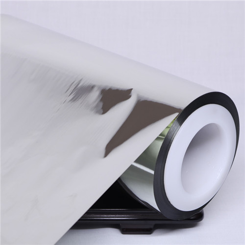
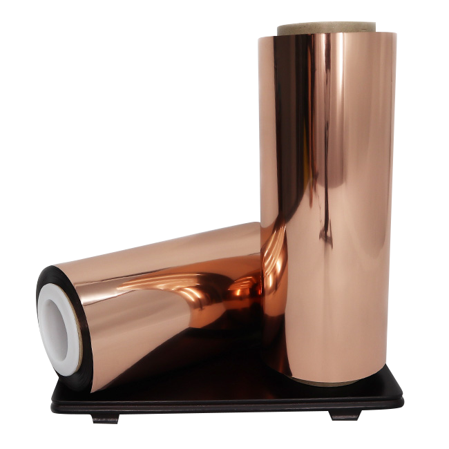
Double side metallized PET film provides a metal surface on both faces of the polyester substrate. This can simplify electrical contact in constructions where either side may need continuity or where folds expose alternating surfaces. The PET carrier contributes handling and dimensional support.
The official double-side metallized PET film VPET-GF02 page describes aluminum on both BOPET surfaces and supplies grade-specific thickness, aluminum-layer, adhesion, uniformity, and surface-tension references. Buyers should obtain the current sheet and confirm which figures are guaranteed.
Surface Resistance Is a Map, Not One Reading
Metallized film surface resistance should be measured at multiple cross-web and roll-length positions, on both sides, and after conversion. Probe pressure, spacing, contact area, temperature, humidity, and surface cleanliness affect the result. A single central reading can hide edge or local variation.
Measure continuity across folds, overlaps, adhesive joints, grounding tabs, and fasteners. If a pressure-sensitive adhesive is used, determine whether it is conductive and whether its resistance changes after heat, humidity, or aging. Ordinary adhesive can electrically isolate two otherwise conductive layers.
Conversion Can Break the Conductive Path
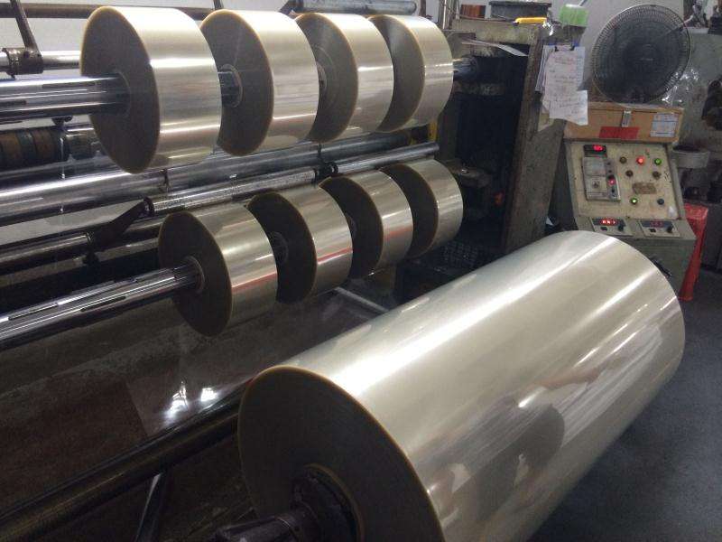
Slitting, die cutting, creasing, printing, lamination, and forming can scratch or separate the metal layer. Tight radii and repeated flexing can create resistance growth that is not visible. Protect both metallized surfaces from contaminated rollers and unnecessary contact.
Run resistance checks after each conversion stage and after environmental conditioning. Inspect cut edges and connection areas under magnification. If the film also provides insulation or decorative functions, ensure the coating or ink does not block required contacts.
Verify Shielding on the Finished Geometry
EMI shielding film approval requires a test method appropriate to the assembly and frequency range. Compare the baseline enclosure, trial film, seam designs, and grounding alternatives. Record attenuation, contact resistance, temperature, humidity, vibration, flexing, and aging as relevant.
A copper foil or conductive fabric may provide a different conductivity, flexibility, thickness, and connection method. Double-side VMPET can be attractive where thinness, weight, and convertibility matter, but it should not be presented as a universal replacement. Use a weighted comparison based on attenuation, continuity, durability, process yield, and total assembly cost.
Grounding Design Determines Whether Conductivity Is Useful
A floating conductive film can redistribute fields without delivering the intended shielding result. Define the ground reference, contact location, contact area, pressure, and corrosion protection. If the assembly opens for service, check whether the ground path is restored reliably after reassembly.
Measure contact resistance before and after thermal cycling, vibration, humidity, and repeated opening where relevant. Avoid relying on visual contact; coatings, oxidation, adhesive squeeze-out, and surface contamination can create an electrically weak joint.
Separate Shielding from Electrical Insulation Requirements
The PET carrier may provide electrical separation while the metal surfaces provide conductivity, but cut edges or exposed metal can create unwanted paths. Identify zones that must conduct, zones that must remain insulated, and minimum spacing around high-voltage parts.
If the film is laminated to another dielectric, confirm breakdown, creepage, bonding, and flame requirements for the complete stack. A shielding improvement must not introduce a short-circuit or safety risk.
Specify Handling for Two Functional Surfaces
Because both faces are metallized, storage and conversion must protect two functional surfaces rather than one. Define interleaf or packaging needs, roller contact, allowable scratches, surface contamination, winding direction, and inspection lighting. Operators should know which contacts are permitted and where conductive continuity is required. Incoming inspection should sample both sides across width and roll length. Retained samples should remain sealed and identified so oxidation, handling damage, or resistance drift can be compared with the delivered condition.
FAQ
Does low surface resistance guarantee good EMI shielding?
No. Shielding also depends on frequency, seams, aperture size, overlap, grounding, geometry, and environmental durability.
Why metallize both sides of PET?
Two conductive faces can simplify contact through folds or allow connection from either side, depending on the assembly design.
Should resistance be checked after die cutting?
Yes. Cutting and handling can damage edges or the metal layer, and the final contact geometry may differ from the flat roll.
Can ordinary laminate adhesive be used at a grounding joint?
It may electrically isolate the surfaces. Confirm whether the joint requires a conductive adhesive, exposed contact area, fastener, or another connection method.
Double-Side Metallized PET for EMI Shielding: Approval Focus
Double-Side Metallized PET for EMI Shielding is best evaluated as part of the complete electrical path. Map resistance across both surfaces, protect continuity during conversion, design reliable contacts, and measure attenuation on the final geometry.
Comment